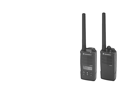
Motorola Radio, and without a CPS cable.
October 2011 - AWal
The title pretty much says it all.
I had purchased one off of ebay (like most ppl for murs radios, retail is
a jyp if you ask me...) and for consistencies sake it was an RDM2070d. These
are the OEM models that are made for WalMart stores (and suposedly Sams Club,
but the Sams in my area still uses the XV2600 that we still have a few of).
The motive behind getting my own radio was simple, people were hoarding the
radios and telexons...It's expected, but I was in a situation that requires
a radio, Cart Associate. I managed to get mine about half-price before shipping
from someone who had accidentally purchased a MURS radio, when they really
needed a VHF radio (apparently the company he worked for had a license to
operate on a specific, non-free frequency).
So, like most electronics I own, I had to crack the sucker open.
I'm not going to provide teardown photos, but it seems like a lot of parts are generic for a
range of radios. The PCB has only one label with the part number and "VHF."
This is no suprise given that MURS is basically just a few frequencies taken
from the original VHF band frequencies and watered down to 2 Watts.
The part that struck my interest was an "M95320" made by STMicroelectronics.
Thats a 32Kbit 3-Wire Serial EEPROM (3-Wire = SPI...which originated from
Motorola...go fig). EEPROMs are easy to dump...let's rip that...
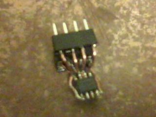
The design was very crude, but my EEPROM burner only took dip-style chips, so
I needed an adapter. With no 1:1 soic to dip available, I made my own.
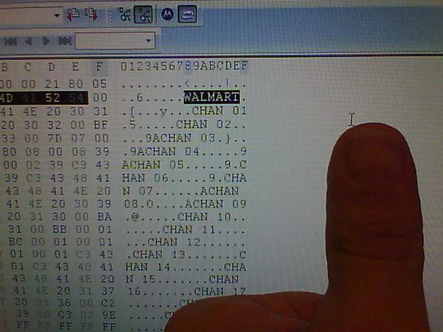
Wait...is that WALMART...in ASCII...wow, Motorola, you made this too easy...
Okay...so first, lets change the WALMART text then re-burn the EEPROM.
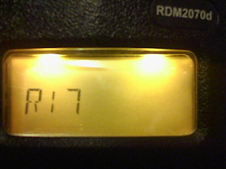
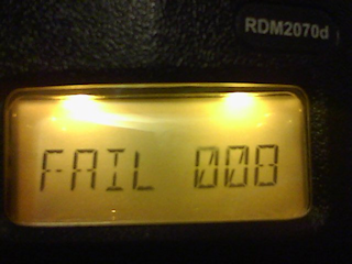
Damn...not that easy. So it looks like there's a checksum or CRC somewhere.
In an attempt to desolder it a second time, a leg broke. It was a good thing
that I took a rip of the chip, or I would've been screwed.
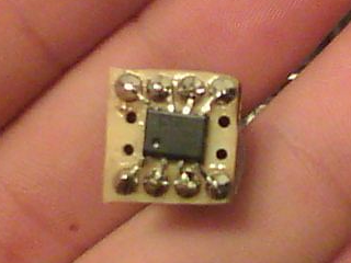
So I bought a replacement chip (or rather...many...since nobody apparently stocks
the dip version of this damn chip).
I'm not too sure if the radios require a chip capable of 1.8v, but they work
with the ON Semiconductor CAT25320 (25320VI to be exact) without issue, so
they probably use low voltage and low rate (ON Semi's only does 10MHz clock tops with 2.5v-5.5v).
It's strange that Motorola would use a High-Speed SPI EEPROM (50MHz Clock @ 5.5v), mabye for factory
programming...but if that were the case they'd just gang program the damn things...
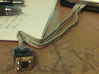
This time I soldered a socket to some wires, then the wires to the board.
Time to prototype :)
There is exactly 20 check digits in the EEPROM's main data section. There
also appears to be code and some other stuff I couldn't quite make out.
The device refuses to operate without an EEPROM, and the same goes for running it
with a blank EEPROM.
--THIS IS PRELIMINARY, I MAY BE WRONG, YOU CAN AND PROBABLY WILL BRICK YOUR RADIO--
EEPROM Memory Map:


0000 - 0139 Main Data

013A - 03FF Unused


0400 - 04AF Data (Purpose Unknown)

04B0 - 07FF Unused


0800 - 0A9F Data (Purpose Unknown)

0AA0 - 0BFF Unused


0C00 - 0D6F Code (Could be data, appears to have vectors though)

0D70 - 0E2F Data, similar to 0400 (Purpose Unknown)

0E30 - 0FFF Unused


Unused sections are filled FF in my EEPROM (Mabye just not programmed)


Main Data (000 - 0139):


Address

     - Factory Default Value

          - Description


0000 - 17 - Unknown - Mabye related to R17 FAIL 008 (from bad EEPROM).


0001 - A1 - 10100001

            ????SL??


            S - Keypad Beep (SB2 at power-on) : 1 = Muted

            L - Keypad Lock (Hold Menu) : 1 = Locked


0002 - 00 - Channel on power on ( 00 = "CHAN 01")


0003 - 00 00 01 07 05 3C 00 00 00 00 21 80 05 07 00 36 00 00 - Unknown


0015 - FF FF FF - Unused


0018 - W  A  L  M  A  R  T  00 - Power Up Text


0020 - 00 - Unknown


0021 - 53 - --Check Digit--


0022 - 00 00 - Unknown (These are probably unused since they aren't checked)


Channel Data:


Address

   - Offset


01 - 0024

02 - 0032

03 - 0040

04 - 004E

05 - 005C

06 - 006A

07 - 0078


These are probably unused, but follow suit, and are in the right places:


08 - 0086

09 - 0094

10 - 00A2

11 - 00B0

12 - 00BE

13 - 00CC

14 - 00DA

15 - 00E8

16 - 00F6

17 - 0104

18 - 0112

19 - 0120


Each Channel Data segment is fourteen bytes long (example used is factory

default "CHAN 01"):


n + 0 - 02 - Frequency (0 = Frequency 1)

    1 - 00 - Code (0 = Code 000, 00 - 7A are valid)

    2 - 02 - Default Frequency (Not sure of use, since these would be)

    3 - 00 - Default Code      (overwritten anyways on reset...)

    4 - C  H  A  N  20 0  1  00 - Channel Alias

    D - BC - --Check Digit--


0123 - 02 9E 02 9E 02 9E 02 9E 02 9E 02 9E - Unknown, probably garbage


013A - FF .. - Unused


--Check Digit-- Computation:


Generate 8-Bit Checksum, then + 5A...yep, that's all there is too it...


Both Main and Channel check digits are computed the same


Let's use an example ("CHAN 01" Factory Default)


               C  H  A  N     0  1     XX

02 00 02 00 C3 43 38 41 4E 20 30 41 00 BC


n  SUM

02  02

00  02

02  04

00  04

C3  C7

43 10A

38 142

41 183

4E 1D1

20 1F1

30 221

41 262

00 262


5A 2BC


BC=-BC - Piece of cake, right?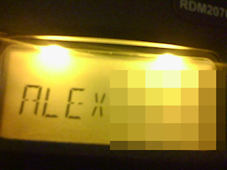
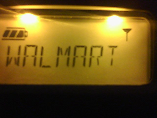
Well, with the proper check digit knowledge, I was able to hex in my own
channel alias and power up text, which was the main goal of this experiment.
Additionally, I think I might have found out how to change the frequencies
on a MURS radio without cloning a VHF radio...if that even works, it's just
a speculation.
TODO:
I need to figure out more bytes...I can probably find the "Roger Beep Tone" bit if I
can locate another compatible radio to listen with...I'm not buying another given
the somewhat heavy price tag...mabye a broken one with FAIL 008 lol :)
If you have anything to contribute, especially EEPROM dumps from other radios
(RDM2080d, RDV2080d, RDM2020, RDV2020, CP110, RDV5100D) I would be interested.
UPDATE!
I've been revamping my design to allow the radio to be charged on a standard dock.
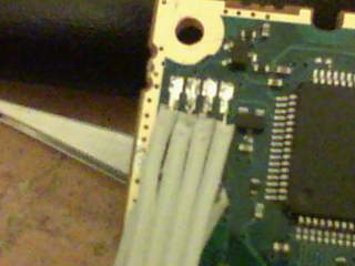
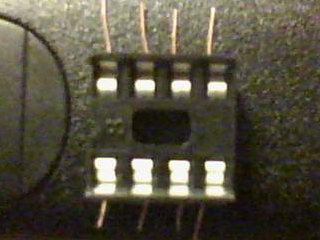
This cleaner design is also a lot more plesant to the eye. :)
